CAD:
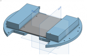
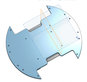
The bottom plate is emphasized here, and the holes along the perimeter are for the HC-SR04 Sensor holders; they will be bolted in. Looking at the bottom view, the four holes in the center are for attachment via spacers to the top plate; this top plate is visible as the gray. Since I didn’t CAD in the spacers, this top plate in the CAD is laying directly atop the bottom one. The large rectangular prisms on either side are stand-ins for the two batteries.
I intend to modify the current designs by adding appropriate holes for wire management in the top plate. This will likely be a second redesign, though. Finally, these plates will be cut out of 3mm-thick plywood via a Laser-Cutter.
In terms of component placement, the motors will be attached in the middle of the bottom plate, and the wheels will extend out where the notches are. The Arduino MEGA + shield, along with the L298N motor driver will be on the top plate; the rest of the components will be secured on the bottom. To be consistent with my hopes for the application of this phase, I will continue to CAD in any extra holes, etc, as I go along.
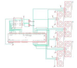
Preliminary Schematic
The green line running through the middle of the motor module pin-out reads “disregard PIN-numbers in favor of PIN-designation; the PIN numbers are different on the L298N I am using”.
edit: I realize now that everything there is illegible… but that was my best screen shot :(. Also, the reason this is ‘preliminary’ because I’ve changed the sensor pin-assignments.