
/sigh
So I redesigned the robot again. and I failed… /sigh
Here’s a quick picture of the CAD model:
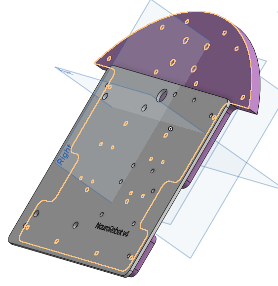
You’ll note that I’ve removed the room for the back sensors. It makes the robot smaller, and moves the wheels further towards the back, so the robot lean distinctly forwards (so it doesn’t move like a chicken). This also removes room for the back sensors… but I’m not using them in the code anyway.
A Few pictures of the build:
Okay I thought it turned out looking SUPER CUTE (and reliable). Here’s a full-blown pic of the front view:
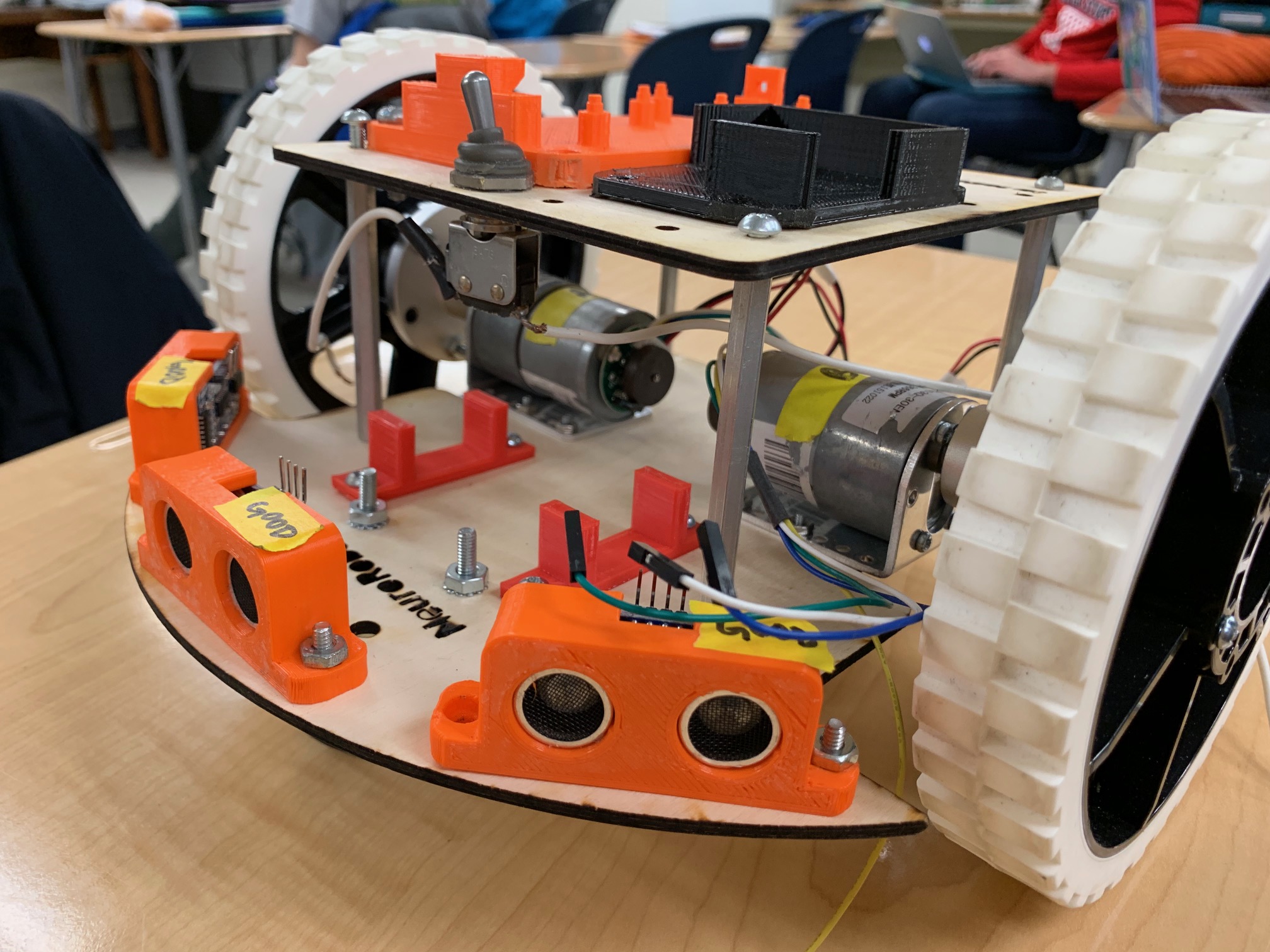
I think I really like where this was going… but let’s break down some of the issues, beginning with the bottom plate.
 I messed up the bolt-holes for the omni wheels again (oops). This wasn’t too big of an issue because I could still use two of them, but it’s still something I should fix.
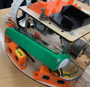
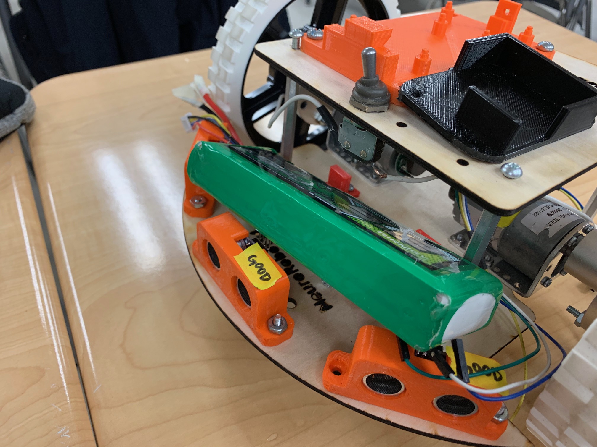
2. I 3D-printed four of these super cute battery-holders, but only actually accounted for two of them. What I also forgot about, however, was that the battery can’t fit in the space between standoffs and I need to account for that.
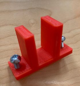
3. I also 3D-printed out similar holders to hold the Robot-XBee Breadboard… but the the top pieces quickly broke off. This is partially the printers part, but primarily mine, because I printed them in the wrong orientation. The stress is placed along that joint, which means I should have many layers running through it (print it sideways). I instead am placing pressure on individual layers, and it takes much less force for one of those to give (print lying flat).
Now for the top plate:
4. I manually shaved down/rounded the edges of both the MEGA holder and the L298N Holder, but it turns out I left too little space between the two… this will definitely need to be adjusted for the next version.