Hello friends!
Fifth time’s the charm! I finally managed to 3D print part-holders and redesign and re-laser cut the chassis. It took a good long while… but here’s what it looks like all put together!
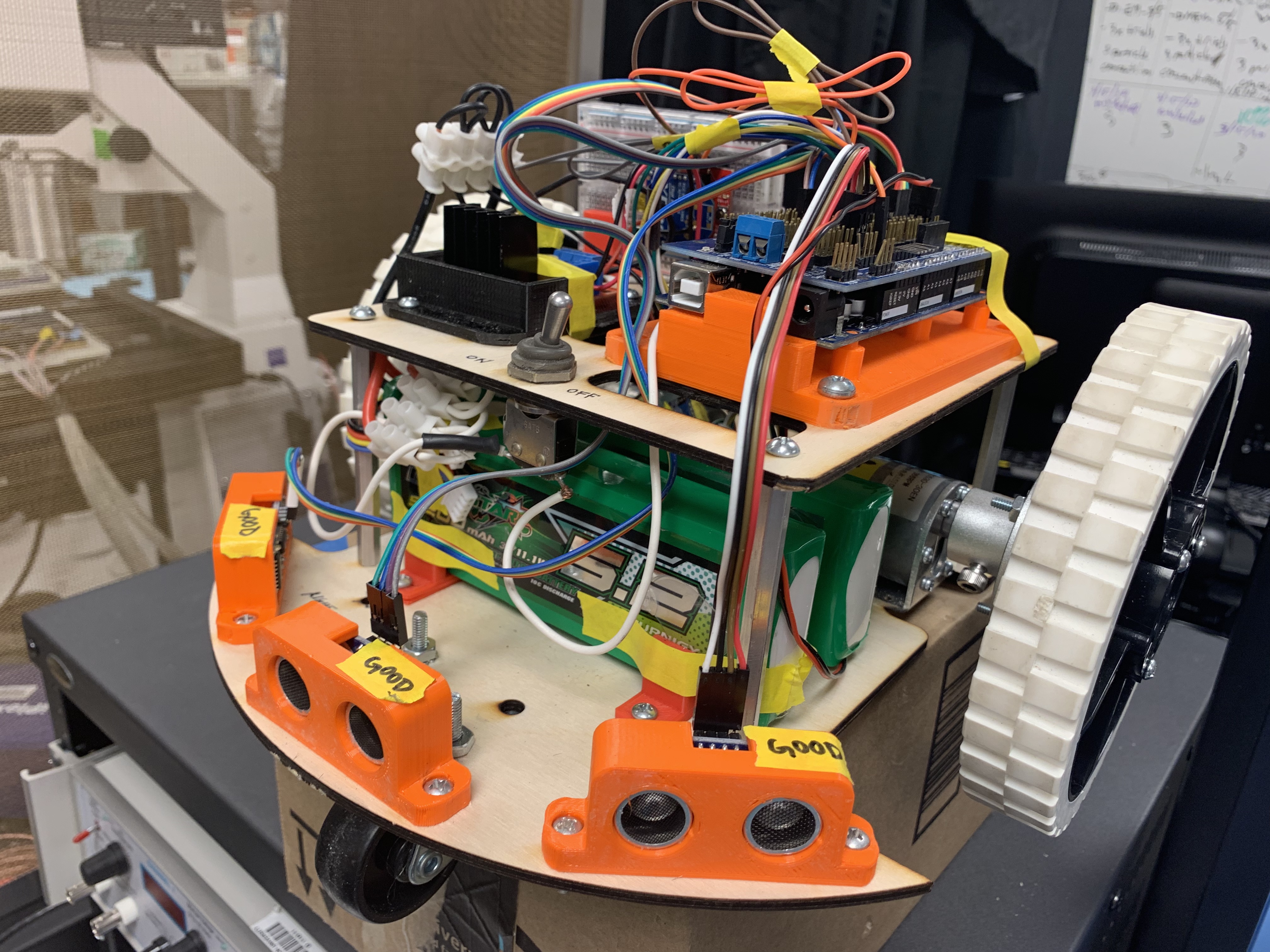
Cuuuute, no? 🙂
From George Mason's Neuroengineering Lab

Hello friends!
Fifth time’s the charm! I finally managed to 3D print part-holders and redesign and re-laser cut the chassis. It took a good long while… but here’s what it looks like all put together!
Cuuuute, no? 🙂
/sigh
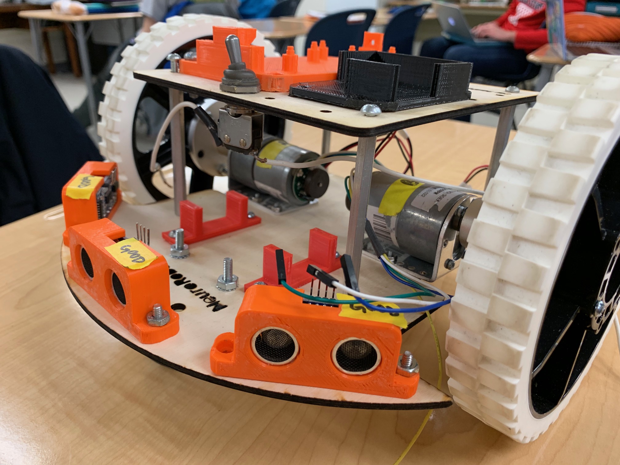
So I redesigned the robot again. and I failed… /sigh
You’ll note that I’ve removed the room for the back sensors. It makes the robot smaller, and moves the wheels further towards the back, so the robot lean distinctly forwards (so it doesn’t move like a chicken). This also removes room for the back sensors… but I’m not using them in the code anyway.
Okay I thought it turned out looking SUPER CUTE (and reliable). Here’s a full-blown pic of the front view:
Hello!
Turns out there are some fancy shenanigans you need to do (know) in order to print on that 3D printer:
Hello!
Here are some notes that might prove useful:
This is all I can think of for now, but I’ll update as needed.
Have a good day!
Hello friends!
There is a new 3D printer in town! Located in room 3204, this super-cool piece of equipment is a MakerBot Replicator and prints using 1.75mm PLA.
(as extrapolated from the example print settings)
Layer height: .2mm
Infill: 10%
Shells: 2
Support: [more on this later]
Raft: generally suggested
Temperature: 215 degrees Celcius
Material: PLA
Transfer data via: USB
181130KA
(format: mostly notes to myself)
So I realized I should probably keep track of robot-chassis CAD versions too– 🙂
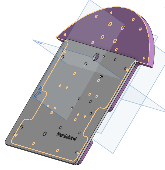
I’m currently on v3, and it will be labeled that way on OnShape until I laser-cut the next version. Current issues:
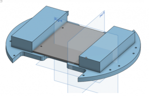
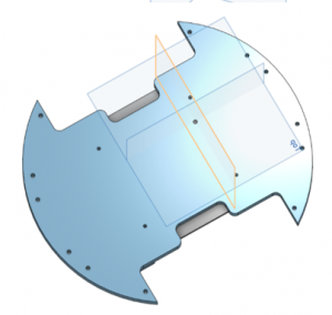
The bottom plate is emphasized here, and the holes along the perimeter are for the HC-SR04 Sensor holders; they will be bolted in. Looking at the bottom view, the four holes in the center are for attachment via spacers to the top plate; this top plate is visible as the gray. Since I didn’t CAD in the spacers, this top plate in the CAD is laying directly atop the bottom one. The large rectangular prisms on either side are stand-ins for the two batteries.
I intend to modify the current designs by adding appropriate holes for wire management in the top plate. This will likely be a second redesign, though. Finally, these plates will be cut out of 3mm-thick plywood via a Laser-Cutter.
Hello!
I inherited this project a few years after its owners left Mason. Originally, I had only a physical robot, but I later gained access to the previous owners’ final code, and some limited documentation.
Here’s a quick breakdown of the original robot (yes, it’s a PDF): Original Robot_Taken Apart
So this is the original design, and my CAD and subsequent designs are coming soon!
Warning: this printer is slow. 🙂
If you would like to know more about 3D printing in general: https://www.instructables.com/id/3D-Printing-Basics/
Note: we’re printing in PLA. Right now, it looks like 30 degrees for the bed and 205 degrees for the extruder works best.
3D Printer being called out: 3914’s very own Monoprice MP Mini
Format: Issue and Resolution. Let’s get started!
There are two possible issues: Heat Creep or Wonky Parts. (Aptly named by yours truly).