Succinct update: stuff stops working after I unplug the USB cable. There wasn’t anything really helpful already in the Arduino forums, so I created a new thread.
Here’s a bulleted summary of what’s in there and what I’ve done since then:
To start
- First response suggest that I’m only drawing 100mA from the 12V batteries unlike the 500mA from the 5V USB line. This could be the reason.
- I mess around with the power supply (more to come) and then realize that I am supplying via a TURNIGY 5A SBEC that supplies a constant 5V and 5A. So that shouldn’t be a problem…
Next I look at where I’ve plugged it in.
From what I can recall, it’s always been plugged into pin A12 on the sensor shield v2.0, and I only remember changing it after I started having issues. So here’s where things get interesting:
- People on the forum wonder why I am powering via pin A12. (I also start to wonder lol).
- Somewhere in the middle of all this, I remove the PWR_SEL jumper on the sensor shield and misplace it. This is what it does:
- “Jumper on: +5 comes from the Arduino. Should be limited to about 300 ma
- Jumper off: +5 comes from the blue terminal strip and an external supply.”
So it’s when I unknowingly/accidentally had/took the jumper off that none of the sensors were working (makes sense because no power to anything on the board). With it back on, I’m back to the original problem where the robot just spins in circles the second it’s disconnected from the USB cable.
I decide to do another test:
I use the XBEEs as a pseudo serial monitor for debugging what’s going on after I uplug the USB cable, since that’s when the code starts malfunctioning.
- I have a quick sketch written up to test the encoders. When I run it w/o the USB cable, it works fine.
- Deduction: the pins on the sensor shield are still receiving power?
- I think to test just the sensors individually, with below loop.
- Lo and behold I get the appropriate ‘Y’ and ‘N’s when the USB cable is plugged in, but don’t receiving anything when it’s just running off the batteries.
byte rx_byte = 0; // stores received byte

void adjust(){
Serial.println(bm.dist()); //so middle sensor
Serial.println(bl.dist()); //so left sensor
Serial.println(br.dist()); //so right sensor

int tooclose = 10;
int justright = 20;
int goaway = 5;

if(bm.dist() < tooclose)
{rx_byte = 'Y';
}else if (bm.dist()> tooclose)
{rx_byte = 'N';
}
}
void setup() {
 Serial.begin(9600);
 Serial.println("Starting up...");
  Serial3.begin(9600); // serial port 3
 //digitalWrite(40, LOW); //interruptPin
  //setSpeeds(100);
}
void loop() {
 adjust();
 if (Serial3.available()) {
 Serial3.write(rx_byte);
 }
}
why do the encoders work, but not the sensors?
I figure it’s just the sensor-pins that are fried, and then switch them to where the encoders were connected.
- Now I’m receiving some data from the sensors.
- New problem: I get appropriate ‘Y’s and ‘N’s when the USB cable is plugged in, and then I get all ‘Y’s as soon as the cable is disconnected.
- I check that the code isn’t just defaulting to the ‘first’ part of the loop. Negative.
- I try a new loop meant to categorize the distances so that I can better understand what’s happening. It’s pasted below, and here are the results:
- I get the appropriate ‘3’, ‘2’, ‘1’ and ‘0’s when the USB cable is plugged in.
- I get all ‘0’s when the USB cable is disconnected.
- In both cases I am receiving this data via the XBees.
int tooclose = 10;
int justright = 20;
int goaway = 5;
if(bm.dist() > justright)
{
 rx_byte = '3';
}
else if (bm.dist() > tooclose)
{rx_byte = '2';
}
else if (bm.dist() > goaway)
{rx_byte = '1';
}
else
{rx_byte = '0';
}
Blink
I’m not really getting anywhere, so I decide to try out the simple Blink test-sketch. I also grab 4 AAA batteries and stick them into a holder to get a nice 9V.
- I plugged the 9V battery into the Arduino’s GND and Vin pins. BLINK worked.
- I plugged the Reverse Polarity Protector into the Arduino’s GND and Vin pins. The Arduino received power, but the code did not work.
- Then I plugged the Reverse Polarity Protector into the Arduino’s GND and 5V pins–it worked! (Now I’m really confused).
Arduino MEGA Sensor shield v2.0
Apparently this shield has a shorting issue. It’s described here, but I don’t understand it completely, so I started another thread asking for an explanation. I think this might be part of the problem… but then why hasn’t it been a problem until now?
Other considerations
See here and here, and I might’ve been in semi-similar situation as here b/c the IDE actually stopped detecting my board for a while…
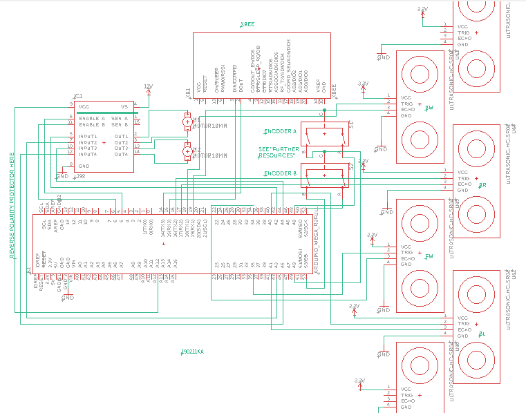
and finally, here’s a picture of my latest schematic: