
Project Goal
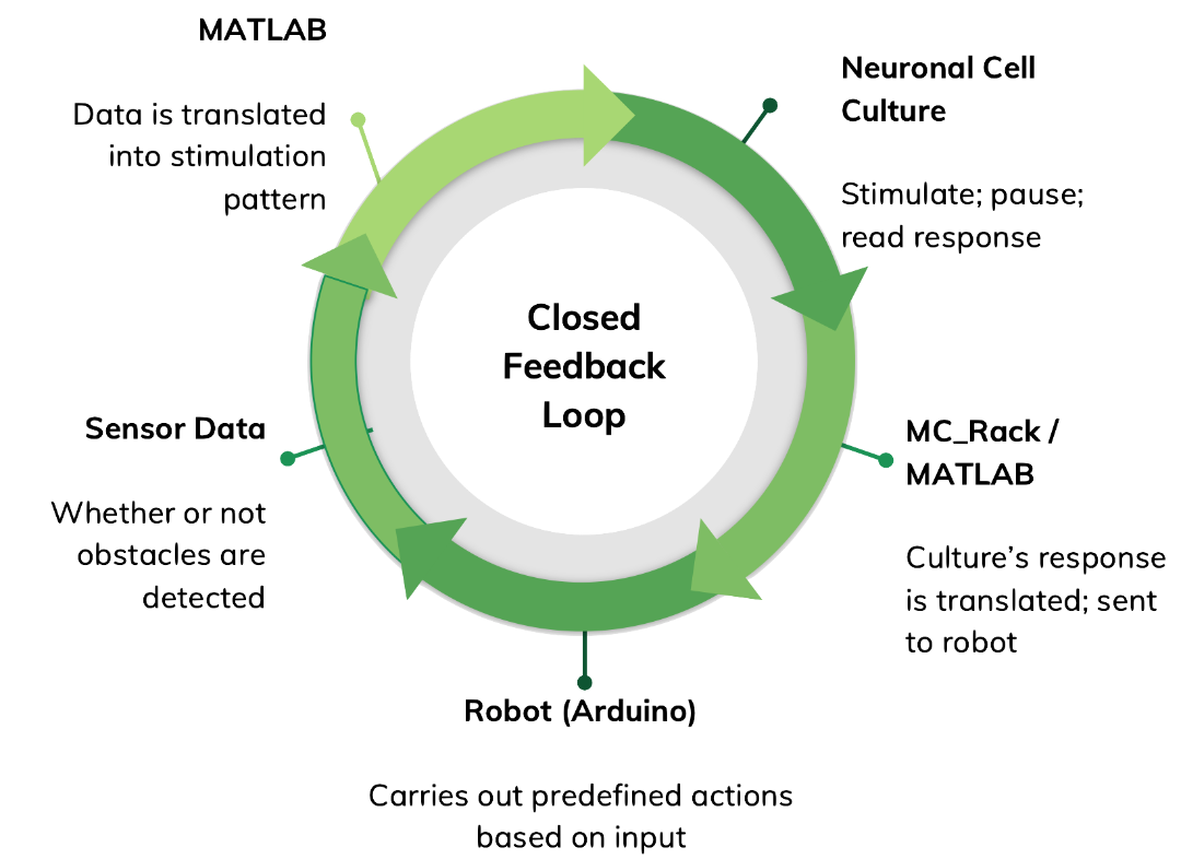
Current research aims to investigate and leverage the learning and computational capabilities of neuronal networks through hybrid neuro-electronic systems. Within this context, the current project focuses on developing a closed-loop system between a neuronal cell culture and a mobile robot, in which the former successfully navigates the latter away from obstacles based on sensor input.
This closed loops begins with the robot itself, which is Arduino-based. It then communicates with a computer via radio modules, delivering sensor input. The computer relays sensor data to the neuronal cell culture in the form of predefined electrical stimulation patterns. It then pauses to read the culture’s response, which is then translated and relayed to the robot in the form of a movement command. This project is ongoing.
Reference Paper: Robot Navigation Using Neuro-electronic Hybrid Systems
Progress
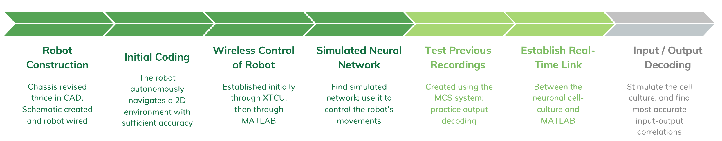
It’s easiest to consider this based on each individual section of the feedback loop. Often enough, I have hit a rut in one area and switched over to a different one to continue progressing. While developed individually, these sections are planned, built, and tested with later integration in mind. (For more detail, see posts under the ‘Latest Updates’ tab).
Here’s a quick summary graphic:
Robot
Building the Robot
 I picked up this project from a previous group, so the NE Lab already had a pre-built robot sitting around. I
didn’t have a schematic and had a few issues with the construction, so I took to rebuilding it.
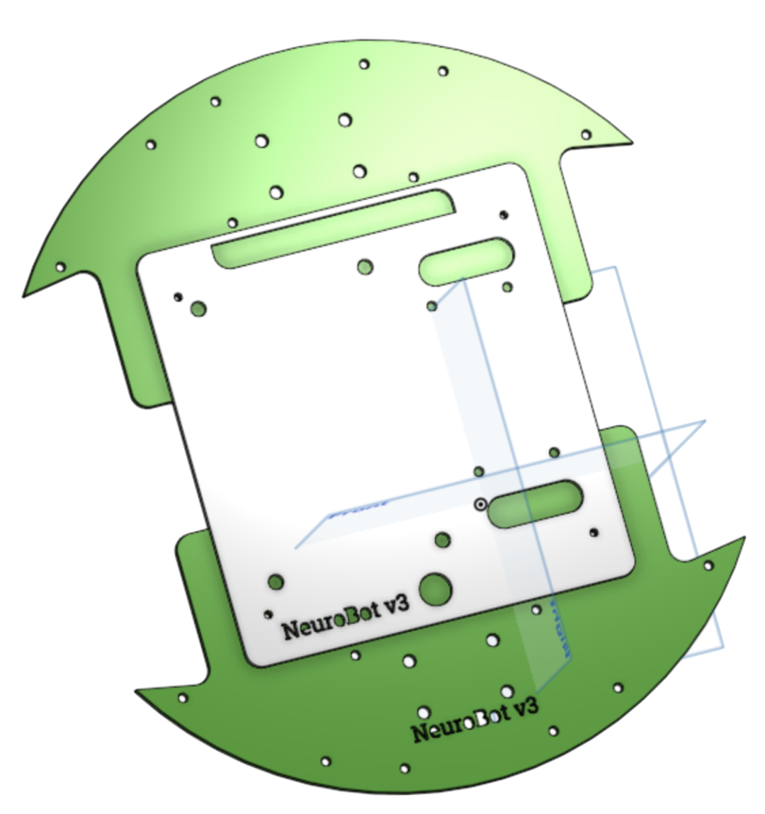
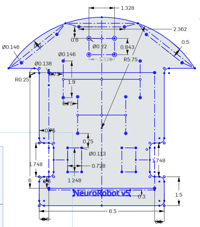
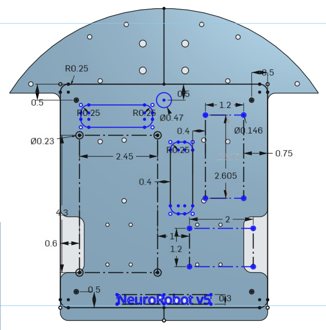
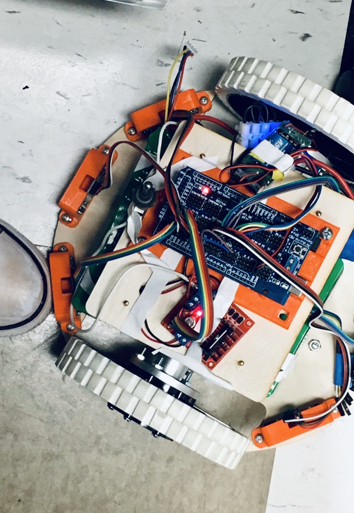
The chassis is laser-cut from 3mm-thick plywood, and the Arduino MEGA and HC-SR04 Ultrasonic Sensors now rest on/in holders downloaded from Thingiverse.This is what the lated CAD model looks like. You can find more information about all the different iterations here.
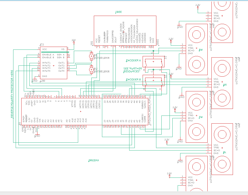
Here’s a picture of the current schematic:
Robot Redesign (v5)
Update: 2019-04-05
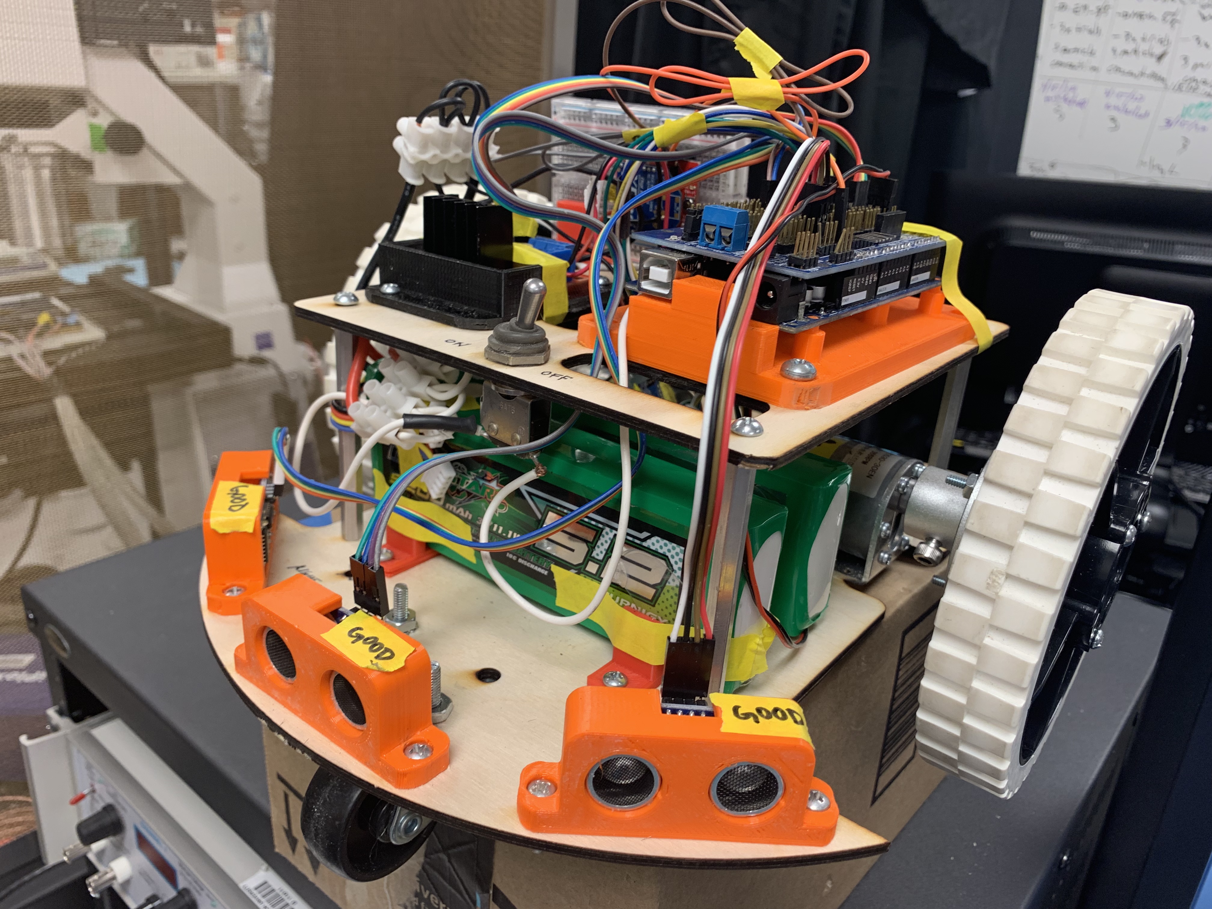
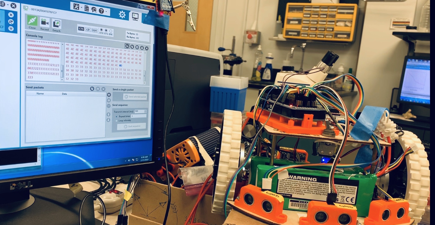
This is what the robot looks like as of late. It looks taller than it actually is, but all the different components (and their placement) are easily visible: the Arduino MEGA + sensor shield, the L298N motor module (in the black holder), the HC-SR04 distance sensors, the XBee-breadboard, the batteries, motors, and wheels.
These two images below are the CAD models of the chassis, which were later laser-cut from 3mm-thick plywood. See more details here.
Coding Different Parts
The robot has two basic programmable components: the sensors and motors. Controlled by the Arduino, these two would work together in autonomous navigation. Before I got to that point, however, I needed to set-up and make sure each part worked correctly on its own. That code can be found here and here.
 Final Autonomous Code
Initially dubbed ‘Roomba’, this code allows the robot to navigate autonomously within any space. This is relevant within the context of the larger project as it establishes the task the neuronal cell culture will later be tasked with.
The main issue here involved battery voltage. Since I used set-times (ex. 100 ms) instead of encoder values to tell the robot how long to continue with each action, the accuracy of the program changed with battery status. (Encoders have since been implemented). It was additionally noted that turn speeds distinctly faster than ‘forward’ or ‘backward’ speeds were required; the small space between the wheels and chassis otherwise got caught on obstacles without triggering the nearest sensor.
See a video of it in action here!
MATLAB — Robot Connection
 Because the task to be completed is navigation, a wireless connection between the cell culture and robot is preferable. Since MATLAB is the intermediary program between the neuronal cell culture and the robot, the link to be established is between itself and the robot.
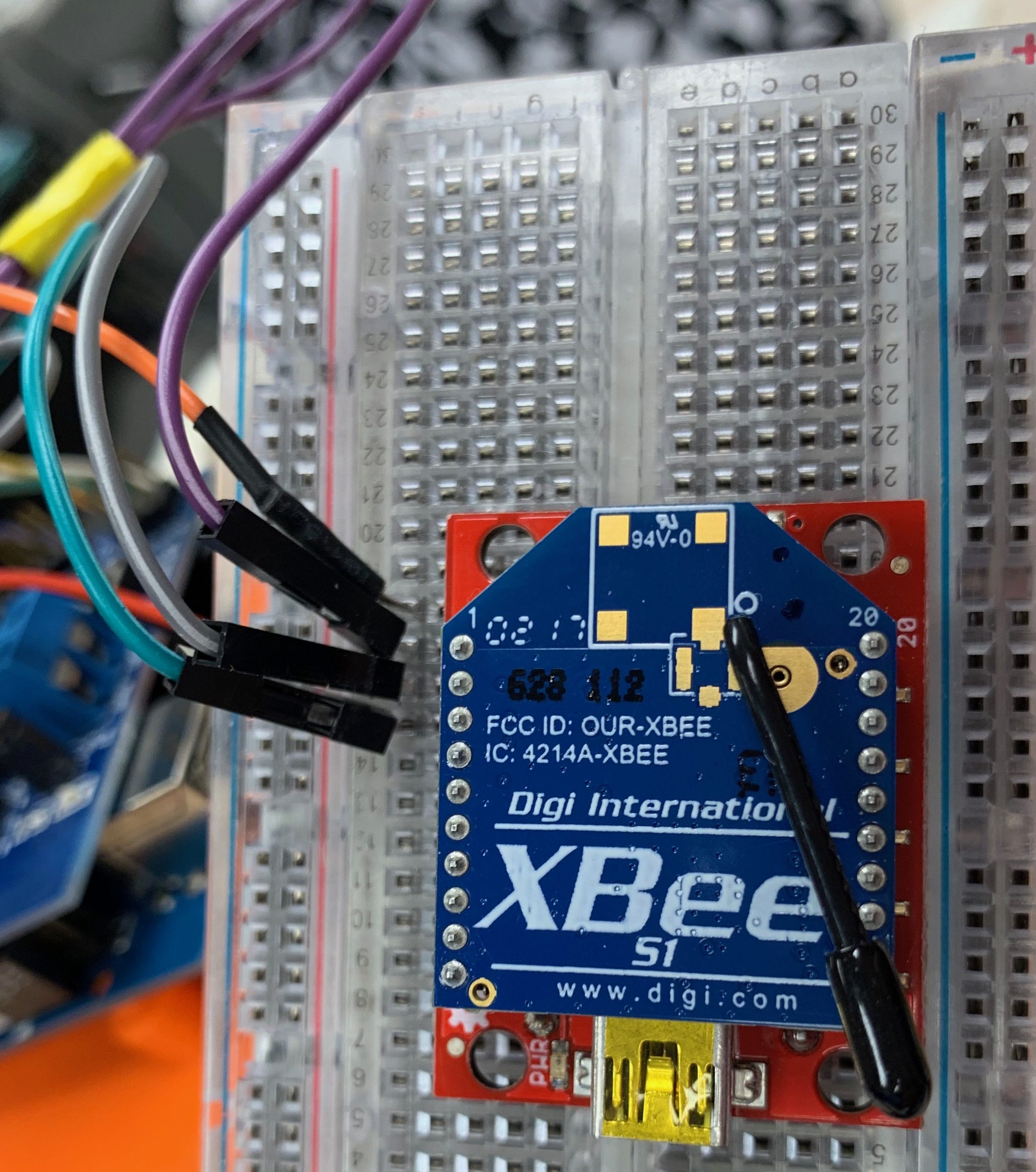
Setting Up XBEEs
XBEEs are wireless communication modules; in this application, regular-antennae, Series 1 modules are being used/adequate. For more information about the XBee ecosystem, see this SparkFun website.
Just like Arduino has its Serial Monitor, XBEE has the program XTCU, which is visible onscreen in the picture below. It is important in getting XBEEs set up and communicating with each other, but can later be substituted with other programs, as is detailed with MATLAB and Arduino below. This post describes the XBEE-setup in more detail.
Controlling Robot via XTCU
The next step in this process was controlling the robot through this wireless connection. Put simply, press a button on the keyboard should move the robot in the requested direction. In this scenario, the keys {i, j, k, l} were used to represent {forward, left, backward, right} respectively.
I was aiming for near instantaneous control–so releasing a key would cause the robot to stop moving–but did not find an appropriate way to represent ‘silence’. A 75ms delay was also placed after each command (say, ‘forward’) because the robot otherwise stuttered and jerked as it attempted to react to input. In the end, I chose the relatively smooth motion provided by the time-delay over the jerky, ‘instantaneous’ control. Further details are provided in this post.
See a video of it in action here!
Controlling Robot via MATLAB
Controlling the robot through XTCU was a nice stepping-stone to controlling it through MATLAB.
Relative unfamiliarity with this program also meant lots of digging along with trial and error.
In the end, I came up with this short loop:
%for MATLAB
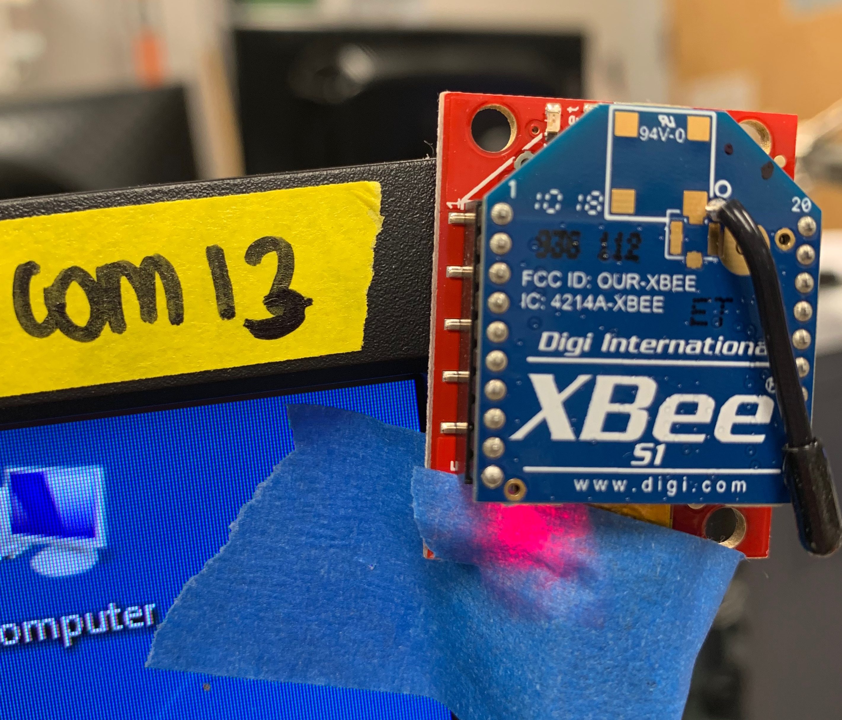
s = serial('COM13', 'BaudRate', 9600, 'Terminator', 'CR', 'StopBit', 1, 'Parity', 'None');
fopen(s);
for c = 1:3
x = getkey('non-ascii')
fprintf(s, x)
end
fclose(s);
The variable ‘c’, which designates how many times MATLAB will send keyboard-commands to the robot, is easily alterable. Find all the exciting details in this here post! and see a video of it in action here!
Controlling Robot with Simulated Neurons
The next step? Controlling the robot with a simulated neural network: I looked for MATLAB scripts with only a few neurons, and actually found a really nice one on the MathWorks online file exchange.
It generates a few variables, but I am taking advantage of one dubbed V, which is a matrix of about 4 x 4000 cells that represent neurons’ spiking (I chose to have 4 neurons). Because each cell contains a decimal number ranging from about -1 to 1, I 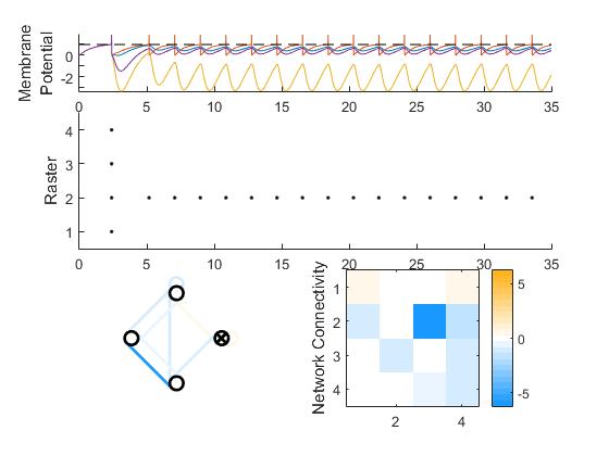 chose two of the four neurons–one for each wheel. I then multiplied their respective outputs from the array by 250 to get the robot’s wheel-speeds; the max wheel speed is 250, and the (+/-) denotes direction. See more in this post.
Here’s some example output (figure is generated automatically).
Sending Packets (MATLAB or XTCU –> Arduino)
In implementing this, I learned how to send larger numbers, or packets, to Arduino from both XTCU and MATLAB to Arduino. The former involves a few clicks in-program, but I wrote a lengthy piece of code for the latter; it is pasted-in and explained here.
Cells — MATLAB Connection
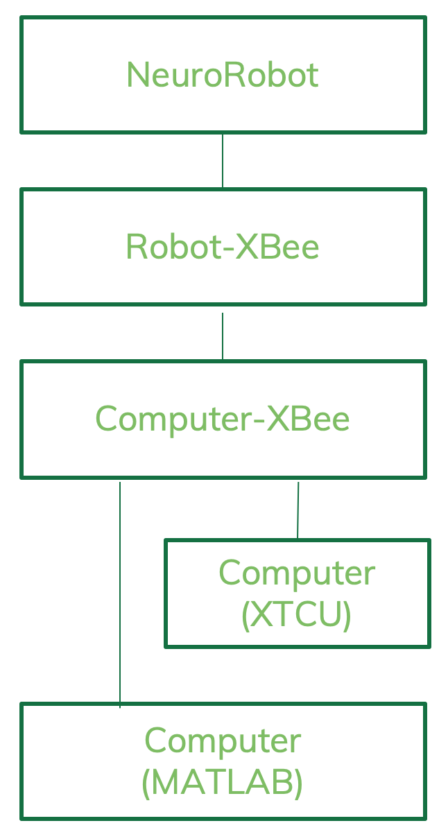
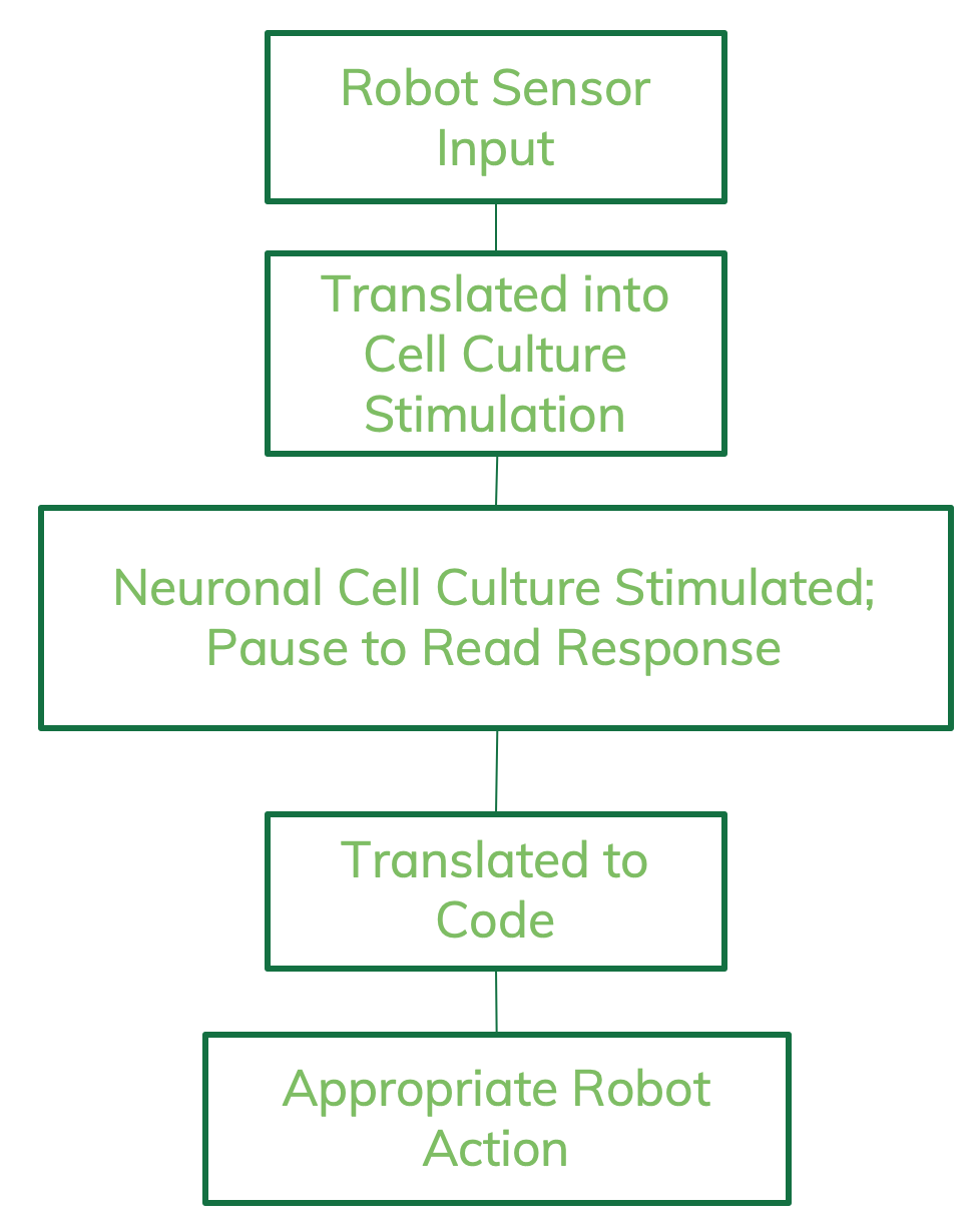 Here’s a simplified flowchart describing how the connection between the robot and neuronal cells (“output decoding”) works. You can find a much more detailed version in this post.
The reference paper correlates a particular stimulation-input to resulting spiking-output (ex. {00, 10, 01, 11}). This is then translated into an action-command for the robot (ex. {RIGHT, LEFT, BACKWARDS, FORWARDS}).
The neural-network simulation I am working with does output an array of spike-times for each neuron. However, this is only useful if it can be correlated back to a particular input.
part 1
Since I can not ‘stimulate’ the neuronal network I am working with, I decided to choose a random pattern and see if I could write code to pick it out. You can find the full description here, but this is the short version: I picked three neurons with the most activity, and then used the line
intersect(A, intersect(B, C)); % A, B, C are arrays of spike-times for simulated neurons A, B, and C
The arbitrary ‘output-pattern’ I decided to search for (see above) was these three neurons spiking simultaneously, and this bit of code accomplishes this objective.
What if the pattern was, say, neuron C spiking 1 second after neurons A and B? Here’s the line that accomplishes it, plus a picture of it working.
intersect(A, intersect(B, C+1)); %C is an array; + 1 thereby increases all its values by 1.
part 2
Next, I needed to control the robot based on the simulated-neurons’ spiking. For the robot, I used the code from this post, and only needed to write a new loop for the MATLAB-end. It is built off of Part 1. Here’s the loop:
for t = 0:50
if(intersect(t,A))
fprintf('k');
end
else if (intersect(t, B))
fprintf('l');
end
else if (intersect(t, B))
fprintf('j');
else
fprintf('i');
end
end
I ran the simulation over 50 time steps. That’s why this for-loop has 50 intervals. Then for each time-step, I’m checking whether both of the designated neurons spiked (then). If they did, then I display the send the robot the appropriate command, coded as one of the letters {i, j, k, l}. You can find a step-by-step explanation of it here.
Right now it’s running pretty quickly–I’ll add time delays when necessary. Here’s a video of it in action!
Explanation of Neural Network Simulation Model
by Cameron McQueen
The leaky integrate and fire (LIF) model can be used to describe action potentials as time related events. A neuron’s cell membrane acts as an insulator. When a current, I(t), is inserted into the neuron, the extra charge, q, charges the cell membrane making it act as a capacitor. As the insulation properties are not perfect, the charge will slowly leak through the cell membrane (Gerstner, Kistler, Naud, & Paninski, 2016). The LIF model defines the dynamics of an action potential by way of electrical coupling with 2 components. The first describes the normal ohmic resistance from the current flowing from one cell to the next. The second component accounts for the effect of the suprathreshold portion of the spike (Lewis & Rinzel, 2003, pp. 283-286).
The applied current can be defined as a function of time, I(t), meaning the current can be expressed mathematically with time as a variable. The voltage potentials of the membrane are expressed in different intervals, the cell membrane’s resting potential (Vr), the membrane’s threshold potential (Vth), the spiking potential (Vspike) and the reset potential (Vreset). These parameters and others related to the cell membranes such as the synaptic strength and speed to name a few, are modified to be dimensionless to describe the two cell system (Lewis & Rinzel, 2003, pp. 283-286).
The membrane potential is then found to be an equation of the resting potential, applied current, past firing rates, inhibitory postsynaptic current, time and the strengths and speed of the synapse.
Citations
1) Gerstner, W., Kistler, W. M., Naud, R., & Paninski, L. (2016). Neuronal dynamics from single neurons to networks and models of cognition.
2) Lewis, T. J., & Rinzel, J. (2003). Dynamics of Spiking Neurons Connected by Both Inhibitory and Electrical Coupling [Abstract]. Journal of Computational Neuroscience, 14, 283-309. Retrieved March 12, 2019, from https://www.math.ucdavis.edu/~tjlewis/pubs/lewisjcns03.pdf.
Establishing Real-Time Link Between MC_Rack and MATLAB
The Neuroengineering Lab uses the MultiChannel Systems (MCS) data acquisition setup to collect data from the MEAs (multi-electrode arrays) holding our neuronal cell cultures. That means the data is read in through the MC_Rack software, which is supplemented by others built by MCS to work in the same environment. I am currently looking for programs that can establish a real-time link between MC_Rack (or the MultiChannel Systems environment) and MATLAB.
I initially looked into the Neuroexplorer (NEX) program, which can do complex analysis and can provide for a direct link to MATLAB. (So it would look like: MC_Rack –> Neuroexplorer –> MATLAB). Unfortunately, NEX4 cannot automatically sort out spike wave-forms, so I looked into a tool called MultiChannel Data Manager, which can ‘translate’ MC_Rack recordings into something workable with MATLAB. Both programs, however, only work with imported data, and as such would not be useful in the long run, where my goal is real-time input.
I want neuronal spiking to be transferred to and further processed in MATLAB. Since the current issue is to figure out how to process the data in real-time, my mentor suggested I look for other research articles that tackle this issue.
Harvesting Cells
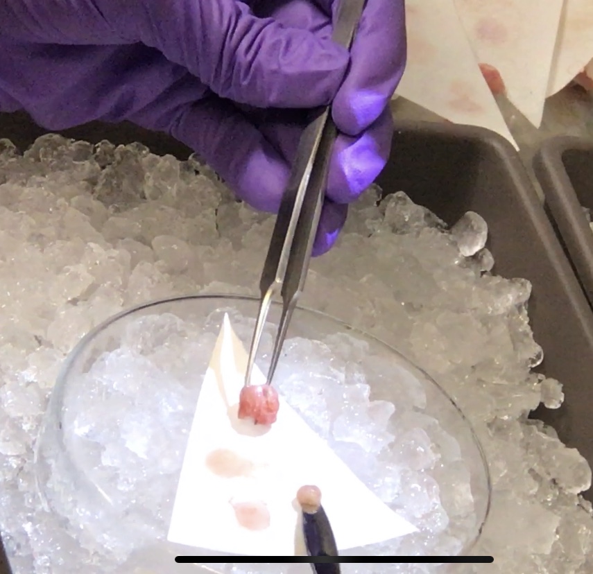
See the full, detailed video of the surgery here!